DCC Turnout Creation in JMRI With TCS Command Stations
Overview
This page provides instructions on how to set up and operate DCC Accessory Decoders for turnouts using JMRI. These instructions are universal to TCS command stations such as the CS-105 or LT-50.
These instructions assume you have already connected your TCS command station to JMRI and have created a profile.
Creating a Turnout using JMRI
There is a convenient user interface in JMRI to create new turnout entries and manage them.
NOTE: JMRI turnouts in LCC can be created to operate any two LCC Events. The turnout throw and close commands have specific LCC events assigned to them.
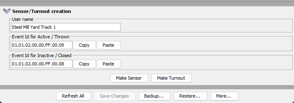
To begin creating a turnout in JMRI, start by opening PanelPro. Next, select "LCC" from the menu bar, then "Configures Nodes." From the LCC Network Tree window which appears, expand the TCS Command Station node and "Open Configuration Dialog" In JMRI. After opening the configuration of the CS-105 (or any other device), at the very bottom there is a box which can be expanded called "sensor/turnout creation". The window will look like this:
.png) To create the turnout, follow these steps:
To create the turnout, follow these steps:
- Type in the name of the turnout to be createed in the "User name" field. (E.G. "Steel mill yard track 1")
- Look at the "LCC Event ID Reference Table" in the section below to determine the Event ID numbers for the address of the DCC accessory decoder.
- Go back to the Sensor/Turnout creation helper in the configuration window and enter the correct Event ID numbers for "Active/Thrown" and "Inactive/Closed". See the example below:
- Once all of the information has been entered, press the "Make Turnout" button.
.png)
The turnout has now been created in the turnout table in JMRI PanelPro! Repeat the steps above for each DCC turnout number to be added. Be sure to use the correct Event ID numbers for each turnout.
To verify that the newly created turnout works, go to the Turnout Table in JMRI (PanelPro > Tools > Tables > Turnouts). Find the line with the user name you just entered. Press the 2-dot / 3-dot button on the UWT to see the turnout change position. The position should be updated on the JMRI screen. Pressing the button on the JMRI screen to toggle the turnout should also update the UWT on-screen in real time.
When finished, the JMRI tables/panels can be saved to an ".xml" file so that all of the turnouts that have been created are remembered by JMRI. See the JMRI help manual for more information.
LCC Event ID Reference Table
To set up the "normal" and "thrown" events for your DCC Accessory Decoder, use the table below. First find the DCC Accessory Address in the left-most column, then enter the 'event ID / address' prefix and append the correct "Normal" or "Reverse" suffix.
| DCC Accessory Address | LCC Event ID / Address | Normal/On | Reverse/Off |
|---|---|---|---|
| 2044 | 01.01.02.00.00.FF | .00.01 | .00.00 |
| 2045 | 01.01.02.00.00.FF | .00.03 | .00.02 |
| 2046 | 01.01.02.00.00.FF | .00.05 | .00.04 |
| 2047 | 01.01.02.00.00.FF | .00.07 | .00.06 |
| 1 | 01.01.02.00.00.FF | .00.09 | .00.08 |
| 2 | 01.01.02.00.00.FF | .00.0B | .00.0A |
| 3 | 01.01.02.00.00.FF | .00.0D | .00.0C |
| 4 | 01.01.02.00.00.FF | .00.0F | .00.0E |
| 5 | 01.01.02.00.00.FF | .00.11 | .00.10 |
| 6 | 01.01.02.00.00.FF | .00.13 | .00.12 |
| 7 | 01.01.02.00.00.FF | .00.15 | .00.14 |
| 8 | 01.01.02.00.00.FF | .00.17 | .00.16 |
| 9 | 01.01.02.00.00.FF | .00.19 | .00.18 |
| 10 | 01.01.02.00.00.FF | .00.1B | .00.1A |
| (...) | (...) | (...) | (...) |
| 100 | 01.01.02.00.00.FF | .00.CF | .00.CE |
| (...) | (...) | (...) | (...) |
| 1028 | 01.01.02.00.00.FF | .08.0F | .08.0E |
| (...) | (...) | (...) | (...) |
| 2043 | 01.01.02.00.00.FF | 0F.FD | .0F.FC |
Alternative Instructions for Determining the Event ID
These instructions are for more advanced users familiar with JMRI, LCC, or debugging platforms. For most users, the table above should be used to determine the Event ID's to use when setting up your DCC turnouts. Keep in mind also that if your LCC netowrk is large, the amount of traffic will be higher and it will be increasingly difficult to find individual events. Try to shut down or isolate as much of your LCC network as possible before continuing.
NOTE: For setting up with a CS-105, a TCS throttle must also be connected and used in LCC mode. Start the UWT-100 or UWT-50 and connect to the CS-105 in LCC mode, then press the accessory button and enter the turnout number you want.
- On the PanelPro menu bar, click the LCC dropdown and select "Traffic Monitor" from the list.
- If not already blank, press the "Clear Screen" button.
- Press the 2-dot or 3-dot button on the UWT to set the turnout to a particular direction.
- Press the "Freeze Screen" button, find the correct Event ID, then select everything after the colon ":" (should be 16 digits with dots between every pair) On the monitor log window you will see a line which looks like this: "... Event Report with EventID:01.01.02.00.00.FF.00.06" immediately after pressing the button. See the example below:
- Note the direction of the turnout, and copy the event ID to the clipboard (or write it down)
- Press the "Freeze Screen" button again to resume the logging.
- Press the 2-dot or 3-button on the UWT to set the turnout to the opposite direction from step 3.
- Press the "Freeze Screen" button, find the correct Event ID, then select everything after the colon ":" (the number will have changed by +/-1 compared to the previous Event ID)
- Note the direction of the turnout, and copy the event ID to the clipboard (or write it down)
- Return to the steps above for creating a turnout.
.png)
Repeat these steps for each turnout to be created.