RTR-MB1
Technical Information
The RTR-MB1 from TCS is an 8-function 21-pin decoder motherboard with integrated Keep Alive® on-board. The RTR-MB1 was designed specifically to fit Athearn Ready to Roll and “Blue Box” diesel locomotives in HO-scale. This motherboard features an on-board regulated 1.5V power supply for incandescent “rice” bulbs, and can also be used with LEDs. Configuration is done via solder jumpers, which is required in order for the RTR-MB1 to function. See the Lighting Wiring Instructions section below for detailed instructions.
The RTR-MB1 has been designed to meet NMRA standards, and is compatible with any NMRA-compliant 21-pin decoder with up to 8 lighting outputs, such as TCS’ WOW121 or EU821 decoders (sold separately). All of TCS' motherboards, including this one, are available for purchase with "high pins" which are compatible with 21-pin decoders from other manufacturers. Since TCS designs decoders with a lower profile, they can be used with a "low profile" pin header. The TCS decoder and motherboard with low profile pins will often fit into installations which would otherwise be impossible due to height clearances.
| Low Profile (TCS Compatible) | High Profile (Non-TCS Compatible) |
|---|---|
.png)
|
.png)
|
| Click to Enlarge | Click to Enlarge |
Wiring Diagram
Shown below is the latest wiring diagram for the RTR-MB1. This diagram depicts the "Revision 5" version of the RTR-MB1, which is the current production version.
.png)
Lighting Wiring Instructions
Information in this section pertains specifically to the revision of the RTR-MB1 released in 2024. The RTR-MB1 was redesigned in July of 2024 to have more feature options for lighting outputs. These options are now configurable through the use of "solder bridge" jumpers located on the top side of the motherboard.
Wiring Instructions for 1.5V Incandescent Bulbs
Perform these steps below to configure the motherboard for 1.5V lighting:
- Solder bridge “1.5V” to “V+” as shown below:
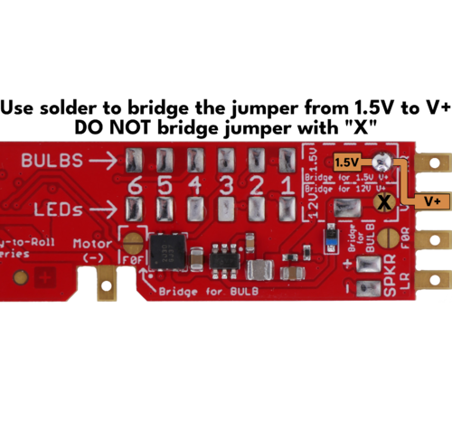
- Connect one wire from each bulb to “V+” OR “1.5V”
- To use 1.5V bulbs for headlights, you must bridge the corresponding jumper(s) for F0F and F0R shown in the diagram below:
- To finish wiring the headlights, connect the second wire to the F0F and F0R pads shown in the wiring diagram.
- To add more 1.5V bulbs, connect one wire to either "V+" pad or the "1.5V" pad, then connect the second wire from each bulb to the numbered pads directly next to the “BULBS” label.
.png)
.png)
NOTE: It is possible to use both incandescent bulbs and LEDs simultaneously. To do so:
|
Wiring Instructions for 12V Incandescent Bulbs
Perform these steps below to configure the motherboard for 1.5V lighting:
- Solder bridge “12V” to “V+” as shown below:
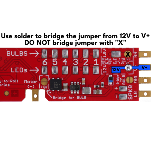
- Connect one wire from each bulb to “V+” OR “12V”
- To use 12V bulbs for headlights, you must bridge the corresponding jumper(s) for F0F and F0R shown in the diagram below
- For Headlights: Connect the second wire to the F0F and F0R pads shown in the wiring diagram.
- To add more 12V bulbs, connect one wire to either "V+" pad or the "12V" pad, then connect the second wire from each bulb to the numbered pads directly next to the “BULBS” label.
.png)
.png)
NOTE: It is possible to use both incandescent bulbs and LEDs simultaneously. To do so:
|