IB-MB3: Difference between revisions
(page creation with basic info) |
No edit summary |
||
| (4 intermediate revisions by the same user not shown) | |||
| Line 38: | Line 38: | ||
==Technical Information== | ==Technical Information== | ||
The {{PAGENAME}} from TCS is an 8-function 21-pin decoder motherboard with integrated Keep Alive® on-board. The {{PAGENAME}} was designed as a universal-fit motherboard, and fits particularly well into many locomotives which were factory-equipped with QSI sound decoders. Unlike all previous motherboard designs from TCS, this motherboard does not include on-board Keep Alive® and instead has a 2-pin plug for connecting an external KA-P Keep Alive® or Soundtraxx "Current Keeper." | The {{PAGENAME}} from TCS is an 8-function 21-pin decoder motherboard with integrated Keep Alive® on-board. The {{PAGENAME}} was designed as a universal-fit motherboard, and fits particularly well into many locomotives which were factory-equipped with QSI sound decoders. Unlike all previous motherboard designs from TCS, this motherboard does not include on-board Keep Alive® and instead has a 2-pin plug for connecting an external KA-P Keep Alive® or Soundtraxx "Current Keeper." | ||
The {{PAGENAME}} has been designed to meet NMRA standards, and is compatible with any NMRA-compliant 21-pin decoder with up to 8 lighting outputs, such as TCS’ WOW121 or EU821 decoders (sold separately). | |||
This motherboard can be used with LEDs thanks to on-board resistors. See the [[IB-MB3#Lighting Wiring Instructions|Lighting Wiring Instructions]] section below for detailed instructions. | |||
{| class="wikitable" | {| class="wikitable" | ||
|+Keep Alive Plug | |+Keep Alive Plug | ||
| Line 50: | Line 54: | ||
|} | |} | ||
The standard variant of the {{PAGENAME}} includes a single 6-pin connector, as well as three 2-pin connectors for the wiring of the locomotive. The corresponding wiring kit can be purchased with the | ===Connector & No-Connector Variants=== | ||
The standard variant of the {{PAGENAME}} includes a single 6-pin connector, as well as three 2-pin connectors for the wiring of the locomotive. The corresponding wiring kit can be purchased with the {{PAGENAME}} to include all of the necessary wiring harnesses which use color-coded wire. The "-NC" variant of this motherboard does not include the plug connectors or harnesses that may be otherwise included in the standard variant of this motherboard; regardless, the "-NC" variant of the IB-MB3 will always include the plug for Keep Alive. | |||
{| class="wikitable" | |||
|+IB-MB3 Wiring Kit | |||
|- | |||
|[[File:IB-MB3 Wiring Kit.png|frameless]] | |||
|- | |||
|''Click to Enlarge'' | |||
|} | |||
===Pin Height Options=== | |||
All of TCS' motherboards, including this one, are available for purchase with "high pins" which are compatible with 21-pin decoders from other manufacturers. Since TCS designs decoders with a lower profile, they can be used with a "low profile" pin header. The TCS decoder and motherboard with low profile pins will often fit into installations which would otherwise be impossible due to height clearances. | All of TCS' motherboards, including this one, are available for purchase with "high pins" which are compatible with 21-pin decoders from other manufacturers. Since TCS designs decoders with a lower profile, they can be used with a "low profile" pin header. The TCS decoder and motherboard with low profile pins will often fit into installations which would otherwise be impossible due to height clearances. | ||
{| class="wikitable" | {| class="wikitable" | ||
| Line 62: | Line 71: | ||
!High Profile (Non-TCS Compatible) | !High Profile (Non-TCS Compatible) | ||
|- | |- | ||
|[[File:IB-MB3 Rev1 Product Picture (Low Pins).png|frameless]] | |[[File:IB-MB3-NC Rev1 Product Picture (Low Pins).png|frameless|link=Special:FilePath/IB-MB3_Rev1_Product_Picture_(Low_Pins).png]] | ||
|[[File:IB-MB3 Rev1 Product Picture (High Pins).png|frameless]] | |[[File:IB-MB3-NC Rev1 Product Picture (High Pins).png|frameless|link=Special:FilePath/IB-MB3_Rev1_Product_Picture_(High_Pins).png]] | ||
|- | |- | ||
|''Click to Enlarge'' | |''Click to Enlarge'' | ||
| Line 76: | Line 85: | ||
===Wiring Instructions for LED Lights=== | ===Wiring Instructions for LED Lights=== | ||
Perform these steps below to | Perform these steps below to connect LED lighting to the motherboard: | ||
Step 1: Connect the Anode (+) wire from the headlight(s) to | Step 1: Connect the Anode (+) wire from the headlight(s) to any available “V+” (BLUE) pad.<br /> | ||
Step 2: Connect the Cathode (-) wire to the F0F and F0R pads shown in the wiring diagram.<br /> | Step 2: Connect the Cathode (-) wire to the F0F and F0R pads shown in the wiring diagram.<br /> | ||
Step 3 (Optional): To add more LED lights, connect one wire to any "V+" (BLUE) pad, then connect the second wire from each bulb to the numbered function pads. | Step 3 (Optional): To add more LED lights, connect one wire to any "V+" (BLUE) pad, then connect the second wire from each bulb to the numbered function pads. | ||
==Previous Revision Information== | ==Previous Revision Information== | ||
''None Available'' | ''None Available'' | ||
[[Category:TCS Products]] | |||
[[Category:TCS Motherboards]] | |||
Latest revision as of 02:46, 17 July 2024
Lua error: Internal error: The interpreter exited with status 1.
Lua error: Internal error: The interpreter exited with status 1.
Technical Information
The IB-MB3 from TCS is an 8-function 21-pin decoder motherboard with integrated Keep Alive® on-board. The IB-MB3 was designed as a universal-fit motherboard, and fits particularly well into many locomotives which were factory-equipped with QSI sound decoders. Unlike all previous motherboard designs from TCS, this motherboard does not include on-board Keep Alive® and instead has a 2-pin plug for connecting an external KA-P Keep Alive® or Soundtraxx "Current Keeper."
The IB-MB3 has been designed to meet NMRA standards, and is compatible with any NMRA-compliant 21-pin decoder with up to 8 lighting outputs, such as TCS’ WOW121 or EU821 decoders (sold separately).
This motherboard can be used with LEDs thanks to on-board resistors. See the Lighting Wiring Instructions section below for detailed instructions.
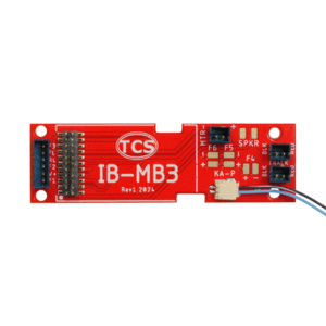
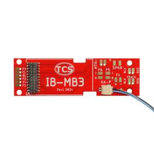
| IB-MB3 | IB-MB3-NC |
|---|---|

|

|
| Click to Enlarge | Click to Enlarge |
Connector & No-Connector Variants
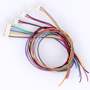
The standard variant of the IB-MB3 includes a single 6-pin connector, as well as three 2-pin connectors for the wiring of the locomotive. The corresponding wiring kit can be purchased with the IB-MB3 to include all of the necessary wiring harnesses which use color-coded wire. The "-NC" variant of this motherboard does not include the plug connectors or harnesses that may be otherwise included in the standard variant of this motherboard; regardless, the "-NC" variant of the IB-MB3 will always include the plug for Keep Alive.

|
| Click to Enlarge |
Pin Height Options
All of TCS' motherboards, including this one, are available for purchase with "high pins" which are compatible with 21-pin decoders from other manufacturers. Since TCS designs decoders with a lower profile, they can be used with a "low profile" pin header. The TCS decoder and motherboard with low profile pins will often fit into installations which would otherwise be impossible due to height clearances.
| Low Profile (TCS Compatible) | High Profile (Non-TCS Compatible) |
|---|---|

|

|
| Click to Enlarge | Click to Enlarge |
Wiring Diagram
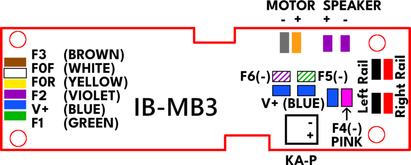
Shown below is the latest wiring diagram for the IB-MB3. This diagram depicts the "Revision 1" version of the IB-MB3, which is the current production version.

The wiring diagram above uses colors for inputs, outputs, and other functions as defined in the NMRA standards for Color Coded Wires.
Lighting Wiring Instructions
Wiring Instructions for LED Lights
Perform these steps below to connect LED lighting to the motherboard:
Step 1: Connect the Anode (+) wire from the headlight(s) to any available “V+” (BLUE) pad.
Step 2: Connect the Cathode (-) wire to the F0F and F0R pads shown in the wiring diagram.
Step 3 (Optional): To add more LED lights, connect one wire to any "V+" (BLUE) pad, then connect the second wire from each bulb to the numbered function pads.
Previous Revision Information
None Available