Booster Adapter: Difference between revisions
m (Changed the word 'Adapt' to 'Connect) |
|||
| (7 intermediate revisions by one other user not shown) | |||
| Line 12: | Line 12: | ||
==Overview== | ==Overview== | ||
<p>The Booster Adapter can be used to | <p>The Booster Adapter can be used to connect different manufacturers' boosters (and command stations) together. This product is intended to offer a quick and easy way to "plug and play" command stations and boosters. Whether upgrading a booster network, command station, or both, the Booster Adapter can help make setup quick and painless! | ||
<p>The Booster Adapter has several on-board plug and terminal connections for: | <p>The Booster Adapter has several on-board plug and terminal connections for: | ||
#LCC CAN- | #LCC CAN-bus | ||
#NCE "Control Bus" | #NCE "Control Bus" | ||
#Digitrax "L.Net-B" | #Digitrax "L.Net-B" | ||
| Line 55: | Line 55: | ||
|- | |- | ||
|DCC Polarity | |DCC Polarity | ||
|This jumper pair may be rotated in order to flip the track output phase of the DCC signal between the LCC CAN-bus and the Control Bus / L.Net-B / CD. This will result in the track output phase of Control Bus / L.Net-B / CD boosters being flipped relative to boosters on the LCC CAN-bus. This is useful when mixing LCC | |This jumper pair may be rotated in order to flip the track output phase of the DCC signal between the LCC CAN-bus and the Control Bus / L.Net-B / CD. This will result in the track output phase of Control Bus / L.Net-B / CD boosters being flipped relative to boosters on the LCC CAN-bus. | ||
This is useful when mixing LCC and non-LCC boosters. If a short circuit is observed when crossing between LCC and non-LCC booster boundaries due to a phase difference, this is an alternative to manually flipping the track wiring at the track outputs. | |||
|- | |- | ||
|LCC Power | |LCC Power | ||
|This jumper pair determines how power will be routed between the LCC RJ-45 jacks (Pin 8 in the LCC- | |This jumper pair determines how power will be routed between the two LCC RJ-45 jacks (Pin 8 in the LCC CAN-bus Standard S-9.7.1.1). The '''Pass''' setting connects pin 8 of the two LCC jacks together so that power passes between them. The '''Output''' setting disconnects pin 8 from passing between the two LCC jacks and requires an external 15VDC power supply in order to feed up to 400mA of current independently into each LCC jack. | ||
|} | |} | ||
Latest revision as of 15:13, 29 November 2022
Lua error: Internal error: The interpreter exited with status 1.
Overview
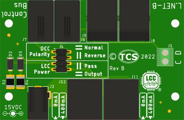
The Booster Adapter can be used to connect different manufacturers' boosters (and command stations) together. This product is intended to offer a quick and easy way to "plug and play" command stations and boosters. Whether upgrading a booster network, command station, or both, the Booster Adapter can help make setup quick and painless!
The Booster Adapter has several on-board plug and terminal connections for:
- LCC CAN-bus
- NCE "Control Bus"
- Digitrax "L.Net-B"
- Lenz "CD"
Some use cases include:
- Connecting a CS-105 to NCE Booster(s)
- Connecting a CS-105 to Digitrax Booster(s)
- Connecting a CS-105 to Lenz Booster(s)
- Connecting a Digitrax command station to NCE Booster(s) (and vice versa)
- Connecting a NCE command station to TCS Booster(s)
- And many more combinations!
The BA-100 can also provide power for other LCC devices distributed around your layout using the on-board barrel jack and an external 15V power supply (not included).
Included In Package
- BA-100 Booster Adapter board x1
- Option Jumpers x4
Physical Interfaces
The Booster Adapter has a few notable physical features:
- 2-pin screw terminal designed for the Lenz style "CD" lines. The "E" line is not supported and may be left unconnected at the booster.
- 2.5mm x 5.5mm barrel jack for Power In
- Configuration Jumpers (see details below)
- Two RJ-11 4-Pin jacks (for use with NCE Control Bus)
- Two RJ-12 6-Pin jacks (for use with LocoNet® / L.Net-B)
- Two "LCC" RJ-45 jacks (1x Front: For T-50; 2x Rear for LCC Bus)
Configuration Jumpers
Refer to the table below for information on the configuration jumpers available on the Booster Adapter:
| Jumper Position | Description |
|---|---|
| DCC Polarity | This jumper pair may be rotated in order to flip the track output phase of the DCC signal between the LCC CAN-bus and the Control Bus / L.Net-B / CD. This will result in the track output phase of Control Bus / L.Net-B / CD boosters being flipped relative to boosters on the LCC CAN-bus.
|
| LCC Power | This jumper pair determines how power will be routed between the two LCC RJ-45 jacks (Pin 8 in the LCC CAN-bus Standard S-9.7.1.1). The Pass setting connects pin 8 of the two LCC jacks together so that power passes between them. The Output setting disconnects pin 8 from passing between the two LCC jacks and requires an external 15VDC power supply in order to feed up to 400mA of current independently into each LCC jack. |
Additional Information
Booster Common
TCS always recommends for users to provide a booster common whenever two or more boosters are in use. This is especially important for boosters that are not electrically isolated. More information can be found on the Booster Interface page under Booster Common.
Booster Interface
Additional information about the booster interface used by TCS products can be found on the Booster Interface page.
