Difference between revisions of "UWT-100"
m |
|||
| Line 114: | Line 114: | ||
==Yard Mode== | ==Yard Mode== | ||
{{:Yard Mode}} | {{:Yard Mode}} | ||
| + | |||
| + | ==Accessory Control== | ||
| + | {{:Universal WiFi Throttle - Accessory Control}} | ||
| + | {{:Universal WiFi Throttle - NCE Macro Control}} | ||
==Throttle Reset== | ==Throttle Reset== | ||
Revision as of 20:42, 23 July 2021
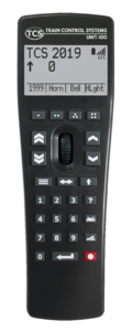
The UWT-100 Universal WiFi Throttle from TCS is the new standard in WiFi control for model railroads. This throttle brings a new level of ergonomic comfort and operational convenience to handheld controls. The intuitive interface of the UWT-100 allows you to focus on the important things - operating and enjoying your trains!
Engineered to work with most current DCC systems, and increase adoption and use of LCC, this throttle relies on the robust and universal standard of WiFi communication and leaves outdated control systems behind. The UWT-100 can be conveniently updated over WiFi, meaning you'll always have access to the newest features and your handheld won't quickly pass out of date.
Contents
Getting Started
Installing Batteries
The UWT-100 is powered using two “AA” batteries. Many battery chemistries can be used, including Alkaline, NiCd, NiMH, and Lithium. The two AA batteries must be installed into the battery holder in the correct orientation in order to power up the throttle. The required polarity of the batteries is indicated within the battery holder. To ensure the battery door is properly secured, press down firmly until you hear a “click.” Once two “AA” batteries have been installed, press and hold any button for 3 seconds to turn on the UWT-100. Once the unit is on, press button 2 to complete the startup process.
Tip: Pressing button 7 at this time will startup the throttle in bootloader mode. Pressing any other button besides 2 or 7 will cancel the startup and power the unit down.
First-Time Setup
When you turn on the throttle for the first time, you will be guided through a quick first-time setup process which includes a quick tutorial. This setup process will enable you to establish an initial WiFi connection. If you would prefer not to use the guide, you may press “Skip.” Otherwise, press “Next” until a scan for WiFi networks is initiated. Once the scan is complete, the throttle will display a list of available WiFi networks. Select your desired network from the list and enter the password if necessary. For help with entering text for your password, please refer to the “Text Entry” section of this guide.
Tip: Digitrax LNWI devices start with a standard prefix. Find “Dtx1-LnServer_(...)” in your network list to connect to your LNWI. For other devices, refer to your manufacturer's manual for information on the default WiFi name.
Once a successful WiFi connection is made, the main Drive Window will appear and you may begin to operate with your UWT-100. Please refer to the “Connection Issues” section of this guide if you experience issues establishing a WiFi or Server connection.
Note: The UWT-100 comes pre-loaded with a single WiFi connection set up, which matches the TCS Command Station, meaning that they will connect to one-another without any additional setup.
Adding a WiFi Network
Once you have successfully connected to a WiFi network, the UWT-100 will attempt to connect to it’s last known WiFi network on startup. If you are in a new location or no known WiFi networks are present in your location, the throttle will display a “No WiFi Found” screen. In order to connect to a new WiFi network, select option 2 “Add New WiFi” which will call up a list of methods for adding a new WiFi connection. This option is also accessible from the menu at any time by navigating to Menu>6 Network Options>3 Add Network
It is recommended that you use Option 1 “Scan for WiFi” to find your WiFi network - this may be a WiFi router connected to your JMRI, an LNWI, or other device. Once the scan is complete, the throttle will display a list of available WiFi networks. Select your desired network from the list and enter the password if necessary.
If multiple connection modes are available on your network, you will be prompted to choose your desired connection mode from a list. You may change your connection mode at any time from the “Network Options” menu. Once a successful WiFi connection is made, the main Drive Window will appear and you may continue to operate with your UWT-100.
Connecting to a DCC System
The UWT-100 can be used with many existing DCC systems. Consult our DCC System Compatibility Guide to learn how to connect your UWT-100 to any DCC system.
Connection Issues
There are two network connections the throttle must make in order to communicate to your command station: a WiFi connection and a Server connection.
Please refer to the UWT-100 Connection Issues section for solutions to common issues.
Using the UWT-100
This section is dedicated to instructions and information on using the UWT-100 throttle.
Power On / Off
To turn on the UWT-100, press and hold any button on the keypad for 3 seconds, followed by button 2 to power up the throttle. When powered up, the throttle will display the main Drive Window - your dashboard for locomotive operations.
NOTE: If you would like to access the bootloader mode for firmware updating, press button 7 instead of 2.
You may choose to shut down the throttle at any time via the Main Menu. To do so, enter the Menu and select option 9 "Power Off." If left idle, the throttle will shut down on its own after a user configurable amount of time (in minutes).
The Menu button will open the UWT-100 Main Menu. There are functions and options in the menu that can customize your user experience and are helpful for throttle operations. Navigating the main menu can be performed in a variety of ways. Rotating the scroll wheel will navigate up or down through the menu items one at a time. The current menu item will be highlighted. Use of the single chevron buttons will also shift the cursor one item at a time, and use of the double chevron buttons will move the page up or down one full screen at a time.
Each menu option corresponds to a numeric keypad button. Pressing the corresponding button will immediately select that numbered menu option, even if that menu option is not visible onscreen. If you choose to scroll for a menu option, press the Enter or Select button. If you would like to know what a menu option does, first consult the Help Text.
The “Help” Button
The Universal WiFi Throttle contains information that explains most menu options and operations. To access these tips, you may press the Help button at any time to access the help text for the currently highlighted menu option. Help text is also available in menus by using the button and which is labeled “Help” on-screen.
A scroll bar will appear on the right side of the screen if more text is available. Scroll up or down to see additional text by using the thumbwheel or the chevron keys. The single chevron keys will navigate one line at a time, and the double chevron keys will navigate one full screen. Pressing the Help button on the Drive Window will bring up the “Function Help” screen. This screen displays all available function buttons, what they do, and their status (on/off). This feature will only display named functions for each function number if the throttle is connected to a JMRI WiThrottle server and has a roster entry whose functions have been defined in [Your locomotive] > Labels and Media > Function Labels.
Programmable Buttons
There are eight buttons on the UWT-100 that can be assigned operations by the user. These buttons can be customized to perform an operation different than their default assignment. The top four buttons, directly below the screen, will always identify their action with an on-screen description. If the description is blank, no action is assigned to that button. You can access button configuration options via the “Throttle Settings” menu. The programmable buttons will adjust based on the configuration in your throttle, command station, and selected locomotive’s roster entry. If you are connected to a server which does not communicate function data such as a LNWI, the buttons will return to their defaults or not display names. When connected to JMRI, the throttle will display the name/number of your locomotive and functions based on your JMRI roster entry. The programmable buttons will display and operate based on the function names as established in your roster entry under [Your locomotive] > Labels and Media > Function Labels.
Text Entry
The UWT-100 has a text entry interface that is used to fill out text-based fields such as WiFi passwords. Whenever the throttle requires text input, it will display the text entry interface. Within the text entry interface, the thumbwheel adjusts the position of the highlighted character. Rotate the thumbwheel to move the cursor to the first character you want to enter, then use the button to ‘Add’ that character. If you make a mistake, you can delete a character using the Backspace button. You may navigate through your entered text using the single up and down chevron buttons.
The double up and down chevron buttons move the cursor up or down one whole line at a time. These buttons also advance the cursor to other pages of characters. To quickly switch between uppercase and lowercase letters, use the Shift key. Letters and special characters can all be entered with the text entry interface. Numbers do not display within the text entry screen and can be entered directly with the throttle keypad When you have finished entering text, press Save or Enter.
Operations
The Drive Window provides an overview of your currently selected locomotive and other important status indicators. When no locomotive is selected, an “E” will be displayed in the top left corner which stands for “Empty”. If you had previously acquired a locomotive address prior to powering down, the throttle will attempt to re-acquire it. In order to operate a locomotive, use the Select Locomotive button. The single dot button defaults to the quick recall function which will swap between the two most recently used addresses/names.
Select A Locomotive
Press the [locomotive] button on the keypad to access the locomotive selection screen. Users are given two options for selecting a locomotive. 1. Enter the cab number manually using the numerical keypad. 2. If the throttle is connected to JMRI, all locomotive IDs (names or numbers) will be automatically loaded from the JMRI roster list. If you have a long roster, you can start entering the address to filter your available options. Use the scroll wheel or chevrons to navigate to the desired locomotive, then press the Enter button to select it and return to the drive window. To assume control of a different locomotive, press the locomotive button on the keypad again.
Digitrax users: If you would like to relinquish control of your currently selected address, enter the Menu and select “Operations” followed by either the “Release” or “Dispatch” options. Once a locomotive address has been released, it will become the first option available in the recall list.
Using Loco Functions
Pressing the numerical buttons on the keypad will operate the function assigned to that number on your locomotive. When a function is turned on, the function number will be displayed on the screen. To select higher function numbers than 9, press the Shift button. The new function page selected will “persist.” You must press the shift button again in order to continue through function pages. This was designed to allow for easy repeated operation of higher-number functions. On the left side of the screen, a small “1” or “2” will indicate that you are controlling higher functions: 1 for F10 - F19, or 2 for F20 - F28.
Reverse Direction
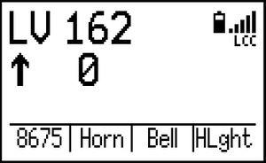
The direction of the locomotive is indicated by the arrow displayed under the cab number and to the left of the current speed. The upward-facing arrow indicates the unit will travel in its forward direction, and the downward-facing arrow indicates it will travel in reverse. Users may change the direction of the unit by using the Reverse Direction button directly below the thumbwheel.
Change Speed
To adjust the speed of the active locomotive, roll the thumbwheel upward toward the screen to increase speed, and downward away to decrease the speed. By default, the single chevron buttons will increase or decrease the speed by 1 step, and the double chevron buttons will increase or decrease the speed in larger steps. The number of speed steps the double chevron keys (fast increment) adjust by are configurable in the “Drive Settings” menu under "Fast Inc/Dec Speed." The chevron keys are also programmable and can be assigned other functions by the user via the “Change Buttons” menu. Refer to the Programmable Buttons section in this guide for more information. The throttle will always display 128 speed step mode but can still control locomotives operating in 28 or 14 speed step mode.
Emergency Stop
The UWT-100 has a unique 3-Stage Emergency Stop function. Some stages will not be supported on certain DCC systems. Stage 1 is supported under all DCC systems that communicate via the WiThrottle Protocol. LCC supports all 3 stages.
Stage 1: Press the E-Stop button once to bring your current locomotive to a stop.
Stage 2: Quickly press the E-Stop button again to stop all of the locomotives on the layout.
Stage 3: Quickly press the E-Stop button a third time to turn layout power off completely.
When E-Stop is initially pressed, a small countdown timer will appear in the drive window. Pressing the E-Stop button again before the timer runs out will escalate the E-Stop to the next stage. To release any of these stages of E-Stop, wait until the countdown has finished and press the E-STOP button again. E-Stop stages can be disabled in the “E-Stop Settings” menu.
Consisting
In-Throttle Consisting
It is common for operators to create and disband Multiple Unit (MU) "consists" during operating sessions. The TCS throttle features a simple method for quickly creating and managing consists that is completely self-contained in the throttle. This method is known as “in-throttle” consisting which operates independently of the command station. In-throttle consisting can be used in conjunction with or independently of decoder-based “advanced” consists.
The in-throttle consisting is active only in WiThrottle Protocol mode (the letters "WT" at the top-right of the screen), supports up to 6 locomotives in a consist, and is capable of controlling the speed, direction, and functions for all locomotives within a consist. The TCS throttle can also select JMRI-created-and-managed consists, as well as "traditional" CV19 consists. For more information on other types of consisting which are not discussed here, see our Help Article on Consisting.
In-Cab Control
Our consisting system features “in-cab control” which allows the user to select the lead locomotive of the consist, effectively putting you “in the cab” as an operator.
When operating with a consist, the Enter button on the throttle can be used to quickly page through consist members and select the lead unit, or active cab. The locomotive chosen as the lead unit can be sent functions that are not sent to the full consist. This can be done using options in the "Consist Functions" menu below.
Managing Consists
When a consist is created, the current cab address will become the first member of that consist. The following options in the “Consisting” menu can be used to manage consists.
Add Loco To Consist - Enter the address of the locomotive to be added, or select from a list. Pressing the Enter button changes the direction of the locomotive being added to the consist.
View Current Consist - Shows all members of current consist and their direction within the consist. Selecting a locomotive from the consist provides options to switch to that cab, remove that member, or change direction.
Clear Current Consist - Disbands the consist, returning all locomotives to independent operation.
Consist Functions - Determines what functions are assigned to the consist or to the selected cab.
Function Routing
Locomotives in prototypical consists exhibit different behaviors depending on their function in the consist. The lead unit will need to use headlights and horns, while trailing units likely will not have operational horns, lights, etc. This behavior can be emulated using In-Throttle Consisting.
While operating with an active consist, access the "Consisting" menu and select "Consist Functions." Each function in the list has the option of being sent to the entire consist, or just to the current cab. Users can quickly toggle these options by selecting a function from the list, selecting "Function Routing," and choosing "Send to All Locos" or "Send to Current Cab."
An asterisk (*) will be shown next to the currently selected option.
Yard Mode
Yard Mode
Overview
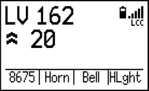
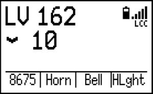
Yard Mode is a special operations mode of the TCS throttle that is suited especially for switching movements. Yard Mode allows users to quickly and conveniently switch between a slow forward speed, a stopped locomotive, and a slow backward speed without managing the direction key and speed knobs/buttons, or keeping track of individual speed steps.
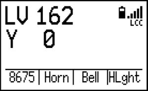
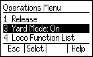
Users may adjust the speed at which their locomotive travels, select between two different speeds for each direction, and quickly stop and start the locomotive when needed. To enable or disable Yard Mode, enter the Main Menu, select "Operations" and then "Yard Mode" from the list of options. When you are in Yard Mode, the direction indicator on the Drive Window will show a letter “Y” instead of an arrow.
Driving a Loco In Yard Mode
UWT-100
To drive the locomotive forward, press and hold the single or double up chevron button. To drive in reverse, press and hold the single or double down chevron button. Your locomotive will drive forward as long as the button is held down. Releasing the button will return the speed to zero and your locomotive will come to a stop.
If you will be traveling a longer distance, and do not want to hold the button down, it is possible to lock-in the current direction and speed of the locomotive by quickly double pressing any of the four Yard Mode buttons. This can also be useful in order to more easily use other function buttons. The locomotive will maintain speed and direction until any button is pressed again, releasing the latch and either changing speed or coming to a stop.
Yard Mode can be used with any locomotive you address. This state will be remembered by the throttle on a per-loco basis even if you select a new address, power down the throttle, and even if you change network profiles/connections!
UWT-50E and LT-50
The UWT-50E and LT-50 operate Yard Mode in the same manner as described above for the UWT-100, except instead of using the chevron buttons, you use the side switches. In the case of the UWT-50E and LT-50, any and all user-configured functions mapped to the up&down side switches will be overwritten by Yard Mode while it is active.
UWT-50P
The UWT-50P Yard Mode operation is unique, thanks to the potentiometer! After entering Yard Mode, you must first rotate the knob to the "center position" which has the distinguished tactile detent. The knob will stop at this position, and will require slightly more force to continue rotating. This stopping point is 0 speed.
On the screen, near the bottom of the "Y" there will be a chevron which will point to the left or to the right. This chevron indicates which direction is "forward" given your current, physical perspective of the locomotive you have selected. Rotating the knob in the same direction that the chevron is pointing will make the locomotive go forward (and vice versa). To change your "perspective," press the direction key. This feature makes it much easier to keep track of which direction of rotation makes your locomotive move which direction on the trackwork.
Unlike in the encoder throttles, for the UWT-50P, Yard Mode is a "global" setting. This means that if you address a new loco, use recall, etc., Yard Mode will stay active until you turn it off; however, the directional chevron/perspective is saved for each locomotive you address you select, even if you select a new address, power down the throttle, and in some cases even if you change network profiles/connections!
Yard Mode Speed Adjustment
In the case of the encoder-based throttles such as the UWT-100, UWT-50E, and LT-50, you may find that the default speeds for Yard Mode (10/126 and 20/126) are not acceptable. Fortunately, these default speeds can be changed on the fly during operation! Rotate the thumbwheel while holding any Yard Mode button, or while the speed is latched, to increase or decrease the speed of the locomotive for the active speed (fast or slow). Both "fast" and "slow" speeds can be adjusted independently (but applies to both directions). Your speed adjustments for Yard Mode will be retained until the throttle is powered off.
Pro Tip: The default speed of Yard Mode for the single chevrons is the same as the Fast Increment speed of the throttle, and the double chevrons default to twice that speed. This can be changed in the “Drive Settings” menu.
In the case of the potentiometer-based throttles like the UWT-50P, in order to make the most effective use of the resolution of the potentiometer, the maximum speed is artificially limited while in Yard Mode. By default, this limit is set to 50/126 speed steps, meaning you can go up to speed step 50 in forward or in reverse. You can raise or lower this limit to any speed (up to 126) through the Yard Mode Max Speed menu. Lower speeds will improve the resolution when rotating the knob in yard mode.
Accessory Control
THIS PAGE IS CURRENTLY UNDER CONSTRUCTION -
Some information on this page has yet to be entered! We are working to fill out the rest of this page as quickly as possible. Please pardon the mess, and watch your step!
Setting Up NCE Macros Using JMRI
NCE Command Stations support a feature called Macros. A Macro is a sequence of actions that happen based on a single user command. Macros can be used for, among other things, sending both locomotive and accessory commands.
| Command Station | Macros Supported |
| PowerCab | 16 |
| SB3a | 16 |
| PowerPro CS02 | 256 |
JMRI supports the ability to activate Macros through a computer interface with an NCE command station. However, WiThrottle Protocol does not provide direct support for NCE Macro activation. These instructions describe a method of JMRI configuration that uses JMRI Routes and Logix in order to activate NCE Macros. The WiThrottle Protocol does provide direct support for JMRI Routes, so we have implemented this workaround.
The TCS UWT-100 throttle supports JMRI Route activation when using the WiThrottle Protocol. This technique can also be used with the WiThrottleTM and Engine Driver smart phone apps. To get started, follow the link below to download the necessary XML file:
JmriNceAddMacroRoutes.xml
It is strongly suggested to put this file into a folder where you can easily access it using JMRI's file browser.
Applying Configuration
If you have an existing configuration, like turnouts or panels in JMRI, use these steps to add the NCE macros to it:
- Start JMRI and load your existing configuration file as usual. You should be seeing your turnouts and your panels now.
- In the PanelPro window select Panels > Open Panels…
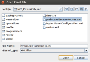
- Find where you have the JmriNceAddMacroRoutes.xml file saved, select it, and click Open. JMRI will now add the Routes and supporting objects for NCE macros from the JmriNceAddMacroRoutes.xml file into your configuration.
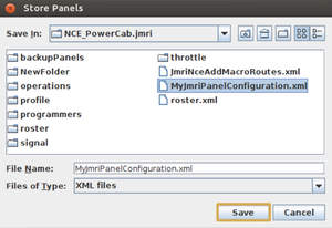
- Save your existing configuration as if you had just added a new turnout to your layout in the Turnout Table. Caution! Saving over an existing configuration could result in a loss of data. It is a good idea to make a backup of an existing configuration before overwriting it, just in case.
You only need to save the configuration one time.
If you do NOT have any regular configuration, then you only need the JmriNceAddMacroRoutes.xml file. Every time you start JMRI, you should click Panels > Open Panels… from the PanelPro window, and select JmriNceAddMacroRoutes.xml. The Macros will be loaded into JMRI. You can make this happen automatically at every start:
- In PanelPro, select the Edit menu item and choose Preferences.
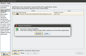
- On the left hand side of the Preferences window, choose Start Up.
- Click the Add drop down button and choose Open file…
- Browse to and select JmriNceAddMacroRoutes.xml and click on the Open button.
- In the lower left hand corner of the Preferences window, click Save. When asked, choose to restart PanelPro.
Customization
User Names
The Routes that were imported for NCE macros can have their User Name customized.
- From the main JMRI PanelPro window, select the Tools menu, choose Tables and then Routes.

- Scroll and select the line representing the NCE Macro, click into the User Name field on that line, and enter the text you would like to show up in the Throttle’s Select Accessory Screen.
Do not forget to save your configuration if you changed any User Names.
Removing Unneeded Entries
The JmriNceAddMacroRoutes.xml file contains configuration for 256 NCE Macros, the maximum supported by any NCE system. To remove clutter in the JMRI Routes table and the Throttle’s Select Accessory Screen, unused Macros (Routes) can be removed:
- From the main JMRI PanelPro window, select the Tools menu, choose Tables and then Routes.
- Press the Delete button for any Macro (Route) you wish to remove.
Do not forget to save the new configuration when finished.
Adding Removed Entries Again
To replace lost or deleted macros, you can perform the steps in the “Applying Configuration” section again; however, when you load JmriNceAddMacroRoutes.xml again, you will get error messages from JMRI that certain objects already exist. Click the “Do not show this message again for this session” checkbox and dismiss the error. The Routes you had deleted will now be repopulated.
Do not forget to save your configuration afterwards.
Theory of Operation
This content of this section is highly technical and not relevant to most users.
The JmriNceAddMacroRoutes.xml configuration is generated using a Python script called JmriCreateNceMacroRoutes.py (Right click on link and select "save link as") . This script is provided in source form for advanced users who wish to make further customizations. The script is provided under a GPL version 2 license.
JmriCreateNceMacroRoutes.py performs the following steps:
- Create a Logix instance called IXNCEM.
- For each Macro starting with 0 and going up to NUM_MACROS:
- Create a Sensor called IS:NCEM:<Macro #>.
- Create a Route called IR:NCEM:<Macro #>.
- Create a Conditional called IXNCEMC<Macro #>.
- Attach the Sensor activation to the Route activation.
- Attach the Conditional to the Logix instance.
- Attach the Sensor to the Conditional as a Conditional Variable.
- Attach a Conditional Action to the Conditional to reset (inactivate) the sensor after a short delay.
- Attach a Conditional Action to the Conditional to execute a Jython script:
- The Jython script provides the business logic to send activate an NCE Macro
- The Jython script is provided as a string embedded in the JmriCreateNceMacroRoutes.py source code
- Enable/Activate the Logix instance.
Throttle Reset
If for any reason the throttle encounters a problem that it cannot recover from, the LED flashlight blinks a diagnostic code, which may be helpful to TCS support. If you encounter this condition, it can be cleared by removing and reinserting the batteries. In the event that removing the batteries from the UWT-100 does not solve the problem, a factory reset may be performed. Navigate to Menu > Settings > Factory Reset (Menu>8>8) to perform a factory reset.
Performing a factory reset will erase all network profiles, user settings, and throttle settings. After performing a factory reset, you will need to re-enter your WiFi connection information as outlined in the section “First-Time Setup.”
