Difference between revisions of "LT Panel"
| Line 24: | Line 24: | ||
*Fascia cover plate screws x2 | *Fascia cover plate screws x2 | ||
| − | === Physical Overview === | + | ===Physical Overview=== |
The LT Panel has a few notable physical features: | The LT Panel has a few notable physical features: | ||
| − | # Green 2-pin Track Output connector with detachable screw terminal connector | + | #Green 2-pin Track Output connector with detachable screw terminal connector |
| − | # 2.5mm x 5.5mm barrel jack for Power In | + | #2.5mm x 5.5mm barrel jack for Power In |
| − | # Configuration Jumpers (see details below) | + | #Configuration Jumpers (see details below) |
| − | # Single "LT" RJ-45 jack(for LT-50 only) | + | #Single "LT" RJ-45 jack(for LT-50 only) |
| − | # Three "LCC" RJ-45 jacks (1x Front: For T-50; 2x Rear for LCC Bus) | + | #Three "LCC" RJ-45 jacks (1x Front: For T-50; 2x Rear for LCC Bus) |
| − | # Bi-color LED for "Track On" | + | #Bi-color LED for "Track On" |
[[File:LT Panel (2).png|frameless|600x600px]] | [[File:LT Panel (2).png|frameless|600x600px]] | ||
| − | === Configuration Jumpers === | + | ===Configuration Jumpers=== |
Refer to the table below for information on the configuration jumpers available on the LT Panel: | Refer to the table below for information on the configuration jumpers available on the LT Panel: | ||
{| class="wikitable" | {| class="wikitable" | ||
| Line 55: | Line 55: | ||
Remove these jumpers to disconnect the low power DCC signals from passing through the panel. | Remove these jumpers to disconnect the low power DCC signals from passing through the panel. | ||
''Note: The LT Panel uses the [https://www.nmra.org/sites/default/files/standards/sandrp/pdf/s-9.1.2_power_station_interface.pdf NMRA S-9.1.2 Full Scale Interface]'' | ''Note: The LT Panel uses the [https://www.nmra.org/sites/default/files/standards/sandrp/pdf/s-9.1.2_power_station_interface.pdf NMRA S-9.1.2 Full Scale Interface]'' | ||
| + | |||
| + | |||
| + | DCC/F is a low-power mirror of the track output from the command station (in this case, the [[LT-50]]). | ||
| + | |||
| + | This circuit is only intended to be used to provide the signal '''from''' the LT-50 '''to''' other devices on the LCC-CAN. | ||
| + | |||
| + | This circuit is '''not''' intended to supply signals to LCC boosters such as the B-106. | ||
| + | |||
| + | This circuit '''must be disabled/open''' if another LCC command station such as the CS-105 (or another LT-50) | ||
| + | |||
| + | is connected to this panel through any of the other LCC jacks. | ||
|} | |} | ||
Revision as of 02:35, 27 August 2022
| LT Panel | |||||||||||||||
|---|---|---|---|---|---|---|---|---|---|---|---|---|---|---|---|
 | |||||||||||||||
The LT Panel is the same fascia panel assembly which comes included with the LT-50.
This product is an expansion panel for an LCC network, such as those created and used by the CS-105 and LT-50. Use this product to expand the number of wired throttles such as the T-50 you can connect to the TCS command station, or to provide an access point and/or power for other LCC devices distributed around your layout.
The LT Panel also includes a jack you can use to connect a Power Supply to power the LCC bus. (Not Included, except with LT-50)
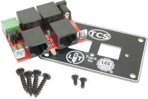
Included In Package
- LT Panel board x1
- LT Panel fascia cover plate x1
- Fascia mounting screws x4
- Fascia cover plate screws x2
Physical Overview
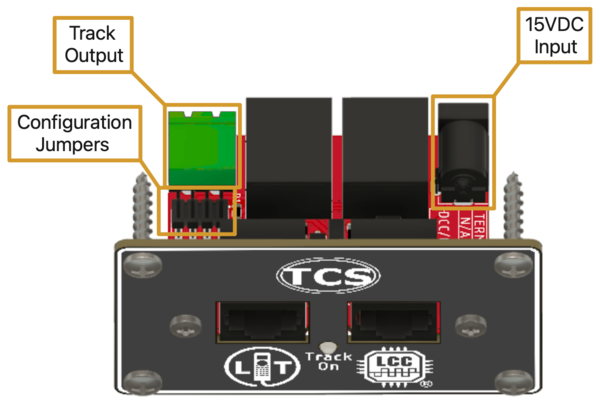
The LT Panel has a few notable physical features:
- Green 2-pin Track Output connector with detachable screw terminal connector
- 2.5mm x 5.5mm barrel jack for Power In
- Configuration Jumpers (see details below)
- Single "LT" RJ-45 jack(for LT-50 only)
- Three "LCC" RJ-45 jacks (1x Front: For T-50; 2x Rear for LCC Bus)
- Bi-color LED for "Track On"
Configuration Jumpers
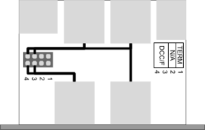
Refer to the table below for information on the configuration jumpers available on the LT Panel:
| Jumper Position | Description |
|---|---|
| (1) TERM | Insert this jumper to add termination to the LCC-CAN bus. An LCC-CAN bus should have exactly two terminators, with one at each end of the bus.
This jumper can (optionally) provide for one of the required terminators. Note: In practicality, a very short (less than 10ft or 3m) LCC-CAN bus can still work reliably with one terminator. |
| (2) N/A | Not Used |
| (3 & 4) DCC/F | Insert these two jumpers to pass the low power DCC signals through the LCC panel (pins 4 & 5 of the LCC-CAN standard).
Remove these jumpers to disconnect the low power DCC signals from passing through the panel. Note: The LT Panel uses the NMRA S-9.1.2 Full Scale Interface
This circuit is only intended to be used to provide the signal from the LT-50 to other devices on the LCC-CAN. This circuit is not intended to supply signals to LCC boosters such as the B-106. This circuit must be disabled/open if another LCC command station such as the CS-105 (or another LT-50) is connected to this panel through any of the other LCC jacks. |

