Difference between revisions of "Booster Interface"
Jump to navigation
Jump to search
| Line 9: | Line 9: | ||
== Power Station Interface on TCS Command Stations and Boosters == | == Power Station Interface on TCS Command Stations and Boosters == | ||
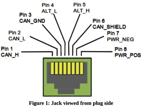
TCS products use the OpenLCB/LCC NMRA S-9.7.1.1 CAN Physical Layer, which consists of an RJ-45 connector routing the CAN signals, Power, and two "ALT" signals: | TCS products use the OpenLCB/LCC NMRA S-9.7.1.1 CAN Physical Layer, which consists of an RJ-45 connector routing the CAN signals, Power, and two "ALT" signals: | ||
| − | [[File:LCC-CAN Jack.jpg| | + | [[File:LCC-CAN Jack.jpg|500px|Copyright 2011-2021 OpenLCB https://openlcb.org/licensing]] |
<br /> | <br /> | ||
Revision as of 15:21, 25 June 2022
TCS command station and booster products (CS-105, B-106, etc...) use the NMRA Standard S-9.1.2 Power Station Interface Full Scale Interface method. TCS command station and booster products are compatible with other manufacturers' products that use the same Full Scale Interface. This includes, but not limited to, command stations and boosters from:
- Digitrax
- Lenz
- NCE
TCS command station and booster products are not directly compatible with the alternative Driver/Receiver Interface method.
Power Station Interface on TCS Command Stations and Boosters
TCS products use the OpenLCB/LCC NMRA S-9.7.1.1 CAN Physical Layer, which consists of an RJ-45 connector routing the CAN signals, Power, and two "ALT" signals:
